47+ solidworks sheet metal flat pattern not working
Im now on another part and I kept getting errors when I was doing it that way so this time I tried starting with a face and just. Offset a plane and on that new plane draw the other profile.

Pin On Solidwork
I would however like to see the part if that is possible.

. Yes its a mess lol. If you have a situation where one of your views is flat or not flat like it should be the fix is pretty easy. Open up the model and go to the offending configuration and click on the.
Also when I bend the part flat its not exactly flat. You began with an block and after that you made your part sheet metal. As shown in the figure below the Flat Pattern view is the same as the front view and shows the part in a bent state.
Additionally merge bodies is required for sheet metal so an additional cutextrude is needed to separate the twins. I tried using the flex tool but it doesnt seem to cooperate too well with what Im asking. Normally you should use the closed corner feature but this feature did not seem to appear.
For a transition like this use a lofted bend. 2 Best Approach To Modeling Sheet Metal Bodies SOLIDWORKS has specific sheet metal features that allow the creation of sheet metal bodies very quickly. The second method I used was to expand out the Flat Pattern in the feature tree and find the sketch Bend-Lines2 could be other numbers shown.
Non-Sheet Metal Flat Pattern. Middle School Drawing Lesson Plans Printable Drawing Lessons For Kids Directed Drawing Lessons For Kids Contour Line Drawing Lesson Plan. I then tried to create a flat pattern from the new sheet metal part.
Search for jobs related to Solidworks sheet metal flat pattern drawing or hire on the worlds largest freelancing marketplace with 19m jobs. From here navigate to the Configurations tab and check the derived configuration Default SM Flat Pattern. The first method I tried was to go to View Sketches.
Hi Im working to a sheet metal and I create a simple circular notch under the Flat Pattern for identify the axis bends intersection with the geometry unfortunately in the drawing on flat pattern view these notches didnt appear usually a simple cut like that must not create problem everything what is created under the flat pattern must. Hi guys I need to get a fat pattern out of a cone with knuckle attached please refer to the model. Get detailed instructions from the leading experts on Solidworks Sheet Metal Flat Pattern.
This toggles the visibility of sketches and if it is off the Bend Lines sketch will be hidden. Be sure to leave a small gap in both profiles. Sdb999 I dont understand this comment.
I have never had a problem creating a sheet metal flat pattern from a mirrored part. I am working with a basic sheet metal part with 3 bend and I am recieving zero errors on the model itself. I deal alot with sheet metal.
After many attempts I still cant get a. In my experience Verdana has been clean not only for Solidworks but for CNC mill laserwaterjet paths also. The Flat-Pattern1 feature is intended to be the last feature in the folded sheet metal part.
When I flat the sheet metal I have got 36461mm. The picture below shows the Reference Configuration for the drawing view selected is DefaultSM-FLAT-PATTERN. Saving Sheet Metal Flat Patterns as DXF Files.
At the sheet-metal feature check auto relief 2mm obround. Having no luck I checked all sheet metal parameters and even went back and checked the original sketches to ensure there are no glitches with the original part. Does anyone know of a way to take a non-sheet metal part for example a flat ring that has flat teeth on the inner surface and fold it out into a flat pattern.
Exporting Sheet Metal Parts to DXF or DWG Files. Create a drawing from a SOLIDWORKS sheet. However in some circumstances when the design demands certain types of geometries the user has the option to use non-sheet metal feature tools and then use the.
All features after Flat-Pattern1 appear only in the flattened sheet metal part. When the Flat pattern drawing view of a SolidWorks sheet metal part displays the part in the bent condition this can indicate an issue with the suppression state of the Flat-pattern feature. Create flat pattern not working.
I do as Mandrake22 suggests and in the mirrored part I InsertBends. Using a plain text is not an issue for my applications. Mirroring Sheet Metal Parts.
Even though SOLIDWORKS has greatly enhanced the sheet metal tools we still get the question asked. Unfold select face and bends Make a cutout at the corners so that the plat does not intersect itself Fold. The recommended way to enter the Flat Pattern view is by the Flatten command on the Sheet Metal tab on the Command Manager.
All features before Flat-Pattern1 in the FeatureManager design tree appear in both the folded and flattened sheet metal part. Dont try to convert or insert bends with sheetmetal. This one isnt too bad.
On the project Im currently working on I drew the outline of the parts and then drew in the bend lines and just used the fold command. 99 of my work involves sheet-metal and i have never seen this. When the Flat-Pattern drawing view of a SOLIDWORKS sheet metal part displays the part in the bent configuration this often indicates an issue with the suppression state of the Flat-Pattern feature in the part file.
That seemed to work pretty well for the most part. Displaying SOLIDWORKS Bend Lines. Im having the hardest time mastering sheet metal.
Improvements to flattening sheet metal parts make flattening succeed for complex. BUT when I create a new drawing and insert a flat pattern view on the sheet the view shows a folded part instead of a flat part. This is added automatically when you create a drawing of a sheet metal part and can help identify the problem.
I converted a 3D part file to sheet metal. To understand this better lets go through the steps of what is suppose to happen when you create a new SOLIDWORKS sheet metal flattened view. When creating a flat pattern drawing view why is the view is not flattened.
Once you make a drawing of a sheet metal part SOLIDWORKS creates a derived configuration of this named DefaultSM-FLAT-PATTERN to be used in drawings. In my experience starting with a sheetmetal feature first produces better results. Wrong flat pattern in View Palette.
Its free to sign up and bid on jobs.
Solidworks Tutorial Y Joint In Sheet Metal Youtube Solidworks Tutorial Solidworks Sheet Metal Drawing

Pin On Solidworks

Pin On Sheet Metal

Pin On Dibujo Tecnico

Pin On Solidworks

Pin On Solidworks
Solidworks Tutorial Sheet Metal Drawings Youtube Sheet Metal Drawing Solidworks Tutorial Solidworks

Solidworks Sheet Metal Tutorial Convert Solid Body Into Sheet Metal Body Solidworks Tutorial Solidworks Sheet Metal

Autodesk Inventor Sheet Metal Tutorial Basics Youtube Autodesk Inventor Solidworks Tutorial Sheet Metal Drawing

Pin On Drafting Cadd

Pin On Sheetmetal Cad Cam Software

Display Sheet Metal Bend Notes 1 By Inserting The Flat Pattern Configuration Into The Drawing As A Regular View Solidworks Property Management Flats Patterns

Pin On Solidworks

Pin On Solidworks

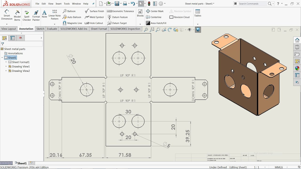
Electrical Box Flat Pattern Drawing Sheet Sheet Metal Drawing Drawing Sheet Sheet Metal